CS 184: COMPUTER GRAPHICS
PREVIOUS
< - - - - > CS
184 HOME < - - - - > CURRENT
< - - - - > NEXT
Lecture #26 -- Wed 4/29/2009.
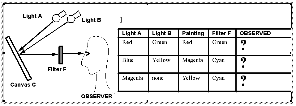
Warm-up Problem:
For
the set-up illustrated below, in which two lights (A & B) shine on a painted
canvas C, which is observed through a Filter (that passes color F),
-- specify what the Observer
sees (Fill in the fields "?"):
Rendering with Participating Media
The intensity and color of light rays may not only be changed when they
interact with discrete surfaces.
When light
rays pass through media that are not completely transparent (water,
vapor, fog, smoke, colored glass ...),
the interaction with these media happens along the whole path,
and the resulting effect increases exponentially with the length of
the path.
(If the effect is small enough, a linear approximation can be used.)
When scenes contain smoke or dust, it may be necessary to take into account
also the scattering
of light as it passes through the media.
This involves solving the radiative transport equation (an integro-differential
equation),
which is more complicated than the traditional rendering equation solved
by global illumination algorithms.
These effects are important when rendering natural phenomena such as: Fire, Smoke, Clouds, Water ...
The photon map method is quite good at simulating light
scattering in participating media.
Transparency
Transparency measures what fraction of light passes through
a surface or body;
that fraction is indicated by the transmission coefficient kt.
Opacity (a) indicates what fraction
is held back; a=1 means: completely opaque.
By definition: kt+a=1
Translucency is a partly transparent object in which the scattering effect dominates; example: frosted glass.
There are many ways to implement partially transparent/opaque objects:
Any of the ???-tracing methods above are a natural way to deal with a (partially) transparent object T;
for instance:
At the surface of object T, we split the ray into a primary ray that
returns the color of object T with some weighted percentage,
and into a secondary ray that passes through the medium and returns
information "from behind" with the complementary percentage.
This information could be further attenuated or discolored, dpending
on the thickness of the body T.
OpenGl offers another mechanism: alpha blending.
A fourth channel a is established
-- in addition to R, G, B.
Thus for each surface, vertex, or pixel we can define four values:
(RGBa).
If a-blending is enabled, the fourth parameter a
determines
how the the RGB values are written into the frame buffer:
typically the result is a linear combination (or blend) of the
contents already in memory and the new information being added.
Filtered Transparency:
Assume that in the frame buffer we have a pixel (Fr, Fg, Fb, Fa),
and we want to place a new pixel with opacity a
in front of it (Nr, Ng, Nb, Na):
We can achieve the desired result with: ( a*Nr
+ kt*Fr, a*Ng
+ kt*Fg, a*Nb
+ kt*Fb, a*Nar
+ kt*Fa );
this corrsponds to placing a filter of opacity a
in front of an already rendered scene.
For this blending function to work, the transparent polygons have to
be rendered after the opaque objects.
For multiple filter polygons, the effect is calculated recursively
back-to-front.
Interpolated Transparency:
In a different situation, we might want to form a composite image from
m
candidate images (e.g. in Image-based Rendering);
In this case, the compositing function might look like: ( sum(Nri)/m,
sum(Ngi)/m, sum(Nbi)/m,
sum(Nai)/m, )
OpenGL provides many different blending functions to take care of many
commonly occuring situations.
Interpolated transparency can be realized by rendering only a subset of
the pixels associated with the image of the transparent object;
in the other pixels, the object behind the "screen-door" object is
rendered.
(the low-order bits in the pixel address determine to which subset
a pixel belongs.)
This technique is limited to a very small number of overlapping transparent
media,
and it can produce some undesirable Moire effects.
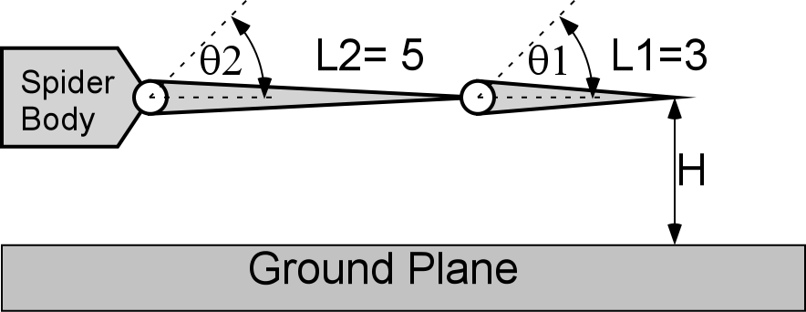
Review of Quiz #3
Write out the (numerical entries in the) Jacobian for this 2-link spider leg
with respect to the height H of its end-effector above the ground plane.
(For convenience, use angles in radians).
ANSWER: ( 3 , 8 )
|
|
Reading Assignments: Whatever gives you the needed background information for your project.
First intermediate report (="AS#9"):
Submit names of team members plus your plan (1 - 5 sentences) for the project by WED April 29, 2009.
PREVIOUS
< - - - - > CS
184 HOME < - - - - > CURRENT
< - - - - > NEXT
Page Editor: Carlo
H. Séquin