First play with Jane Yen's gear animation movie to get a feel how properly designed gears are supposed to work.
To dive deeper into the construction of gears, there are a few files from my own experiments that reveal the function of various parameters. With the file gear.slf you can study how the contact point between the wheels moves as the wheels turn and see how large the teeth have to be made so that the wheels always stay in contact (in both directions) as the wheels turn. Find out at what tooth size interference occurs.
Using the useful pieces of this file, you could try to build your own true gearwheel generator. -- along the logical steps that one would use to design a classical mechanical gear. Don't worry about the module m, since this is just a scale factor on the whole gear pair. Make sure you can easily select one of the two standard pressure angles. Set the addendum and dedendum to their usual default values.
Since it is not totally trivial to understand and control the involute that defines the contact faces of the teeth of a gear wheel, I have created gear2.slf in which I have already calculated the adjustment of the top of the cogs to the addendum circle. (You can still change it with the the "cog face sweep factor.") Now you can focus on combining the two opposite flanks into a single cog.
If you are tired of struggling with making a decent gear wheel face, then gear3.slf will show you one way of doing it. In this code, I am starting at the center and make one complete cog, including space in-between and fillets, and also the axle hole ...
Since the number of teeth may vary, you will have to add or delete geometry as some of the sliders are moved -- not just modify vertex coordiantes or transformation matrices. The demo file Instancing.slf shows you how to do this cleanly by using the tcl commands "slide create point", "slide delete face", etc. You can combine the useful parts of these two demo files to make a generator that gives properly designed gearwheels by default, but with an adjustable number of teeth and pressure angle. Make sure that you get this working properly in 2D first. Now add the bottom face and the side faces to make a 3D extruded spur gear.
Design an interlocking pair that properly moves under slider control. Choose one of the standard two pitch angles. Make sure that there is no interference. Calculate the contact ratio for your gears and make sure it is larger than 1.2; if not, make the necessary fixes. Then make your wheel 3D -- a simple sweep along a straight line segment will do the trick !
If that step seems too tough for you, you may omit it and conically project one tooth directly towards the shared axle-intersection point (shared apex of the 2 cones). You then instantiate the bevelled tooth around the whole perimeter of the bevel gear (i.e., the axis of the cone defining the bevel gear).
Finally construct a suitable supporting disk (the hub) for the teeth with an axle hole in it. The output should be suitable to produce STL descriptions of gears that can be fabricated on an FDM machine; the gears should lie flat on the x-y-plane and their teeth and teeth faces should point slightly upwards.
Ideally, you have an extra slider that controls the angle beteeen the axles of the two wheels (say from 0 degrees to 90 degrees). In any case, make a "movie" SLIDE file, that shows the two conical gear wheels turning. For this, you have to make sure that you adjust the rotation phases of the individual gears so that they properly interlock. Most of this can be taken over from Jane Yen's gear animation movie; it may also may come in handy as a source of inspiration and tcl program code.
When designing a suitable Platonic or Archimedean polyhedron with holes to hold the axles for the wheels, these files may be useful: CS285/CODE/REGPOLY/{ octa.slf , cubocta.slf , or icosidodeca.slf -- and also: Tcube.slf , Tocta.slf , Tdodeca.slf , Ticosa.slf , Ttetra.slf }. Add sink holes for the axles at each face center using boolean operations.
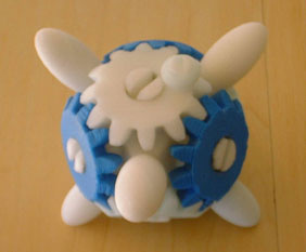
Here is a project done in Spring 2000.