 _Step
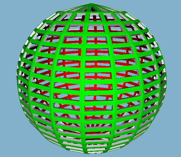
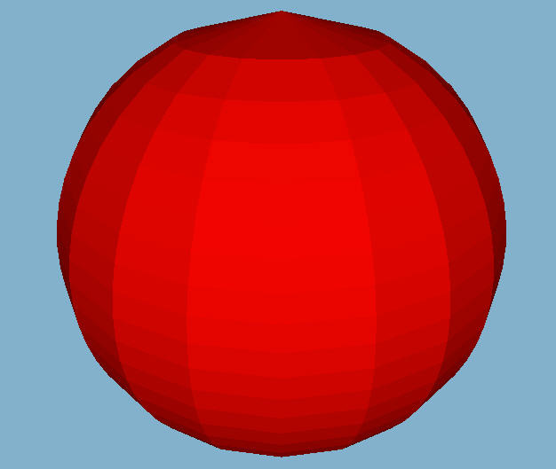
#0: The starting Sphere -- green on the outside, red on the inside.
_Step
#0: The starting Sphere -- green on the outside, red on the inside.
 _Step
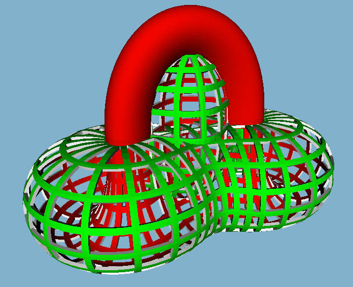
#1: push the South Pole through the North Pole
_Step
#1: push the South Pole through the North Pole
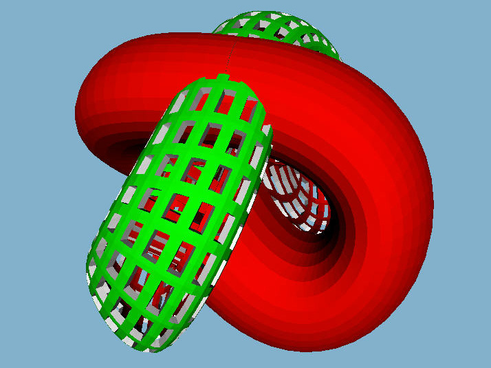
 _Step
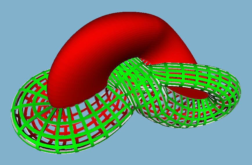
#2: Pinch the red South Pole bulge to push its front to the back, and vice
versa.
_Step
#2: Pinch the red South Pole bulge to push its front to the back, and vice
versa.
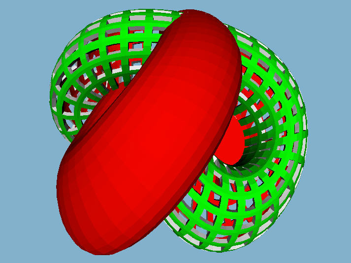
 _Step
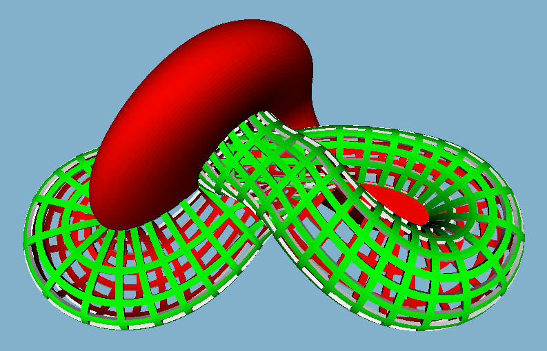
#3: Continue the process of bulging out to the front and back, now seen
from below.
_Step
#3: Continue the process of bulging out to the front and back, now seen
from below.
 _Step
#4": Start to twist the figure-8 shaped "inner tube" at the bottom.
_Step
#4": Start to twist the figure-8 shaped "inner tube" at the bottom.
 _Step
#5: Continue that twisting motion through about 270 degrees until the red
ear drums start to face upwards.
_Step
#5: Continue that twisting motion through about 270 degrees until the red
ear drums start to face upwards.
 _
_ _
_ _Step
#6: We are at the half-way point; this is the famous Morin surface !
_Step
#6: We are at the half-way point; this is the famous Morin surface !
 _Step
#7: Push the red tube crossing the top downwards to get to the equivalent
twisted state of Step #5.
_Step
#7: Push the red tube crossing the top downwards to get to the equivalent
twisted state of Step #5.
 _Step
#8: The twist of the red "inner tube" is being reduced.
_Step
#8: The twist of the red "inner tube" is being reduced.
 _
_ _Step
#9: The un-twisting motion has been completed; result from above and below.
_Step
#9: The un-twisting motion has been completed; result from above and below.
 _Step
#10: The front and back bulges are being retracted, to make a simple green
hump at the top.
_Step
#10: The front and back bulges are being retracted, to make a simple green
hump at the top.
 _Step
#11: Almost done, we just need to retract the green bulge down to the South
Pole.
_Step
#11: Almost done, we just need to retract the green bulge down to the South
Pole.
 _Step
#12: The sphere has been turned inside out.
_Step
#12: The sphere has been turned inside out.
 _
_ _
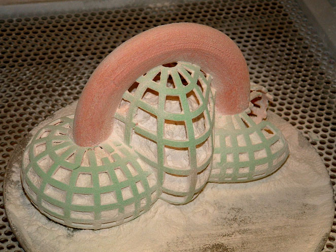
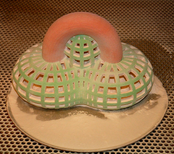
A first, not all-too-successful attempt at building a physical model of
Step #3.
_
A first, not all-too-successful attempt at building a physical model of
Step #3.
 _
_ _
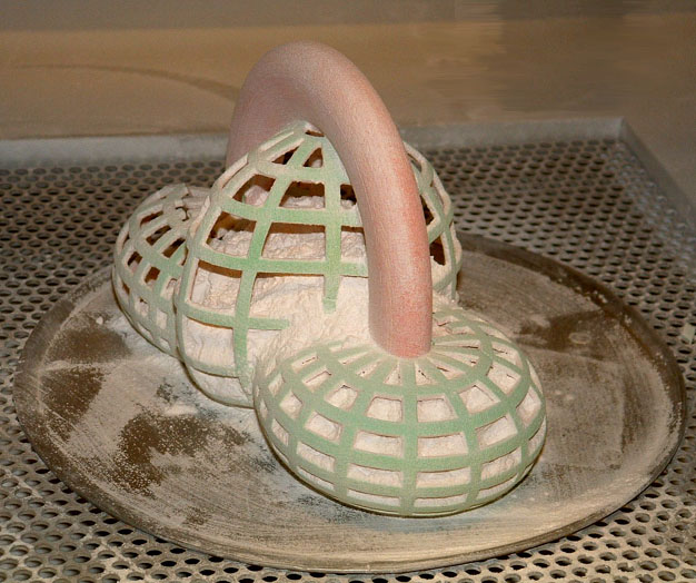
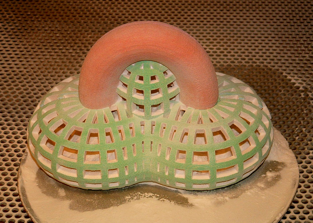
A more robust model with thicker struts of Step #3 in the sequence.
_
A more robust model with thicker struts of Step #3 in the sequence.
 _
_ _
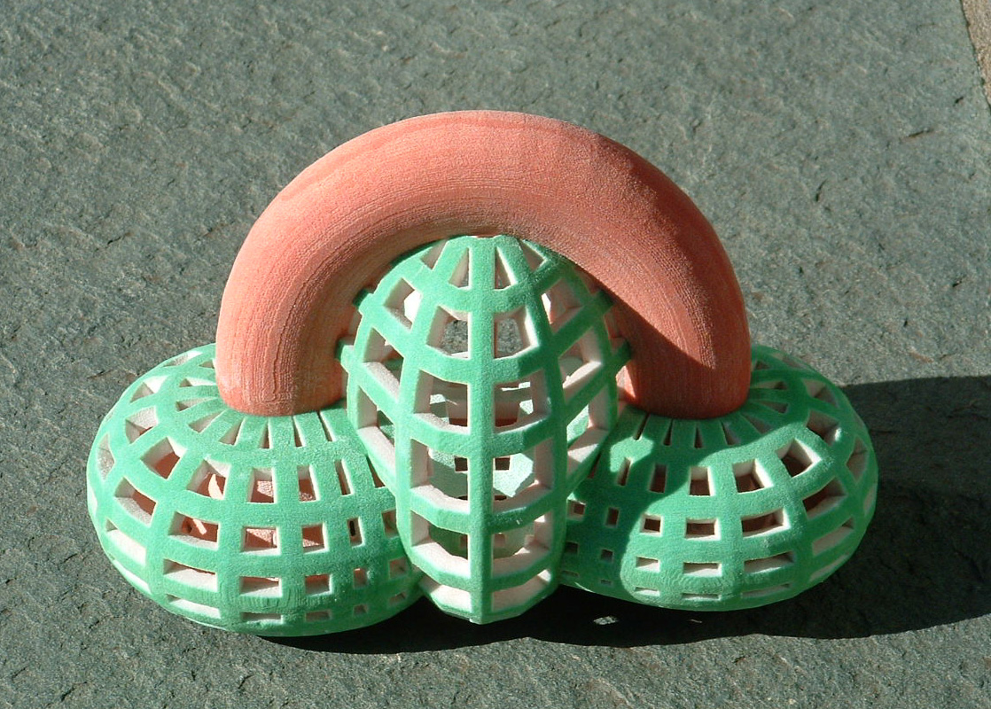
A model of Step #2 in the build phase.
_
A model of Step #2 in the build phase.
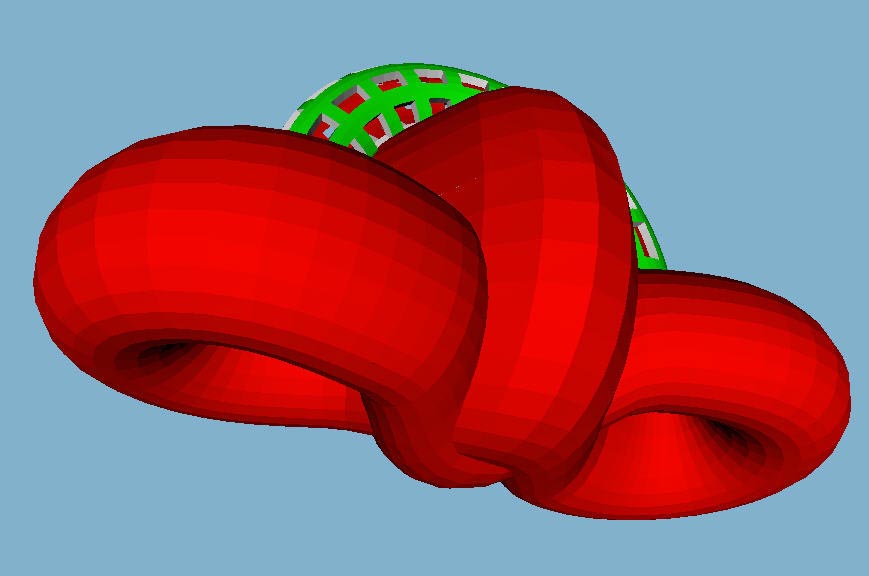
 _
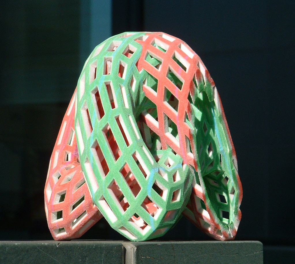
A successful model of the half-way point (Morin surface) in a different,
fully gridded style.
_
A successful model of the half-way point (Morin surface) in a different,
fully gridded style.
 _
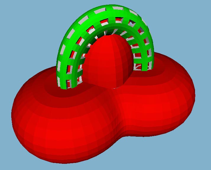
_ _
And a cut-away model of the same step to show what happens inside the lobes.
_
And a cut-away model of the same step to show what happens inside the lobes.