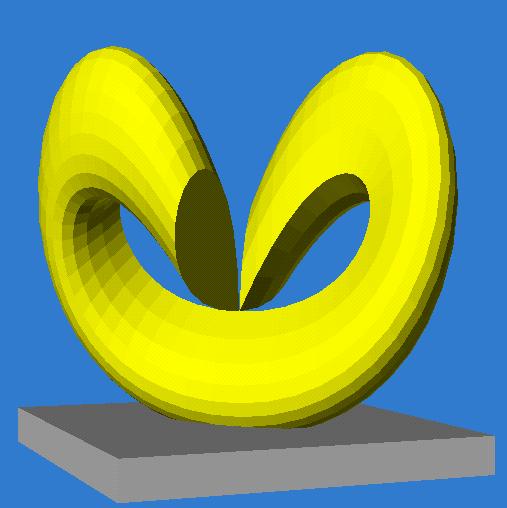
 Computer
rendering of Morin's Surface by John Sullivan.
Computer
rendering of Morin's Surface by John Sullivan.
Computer
rendering of Morin's Surface by John Sullivan.
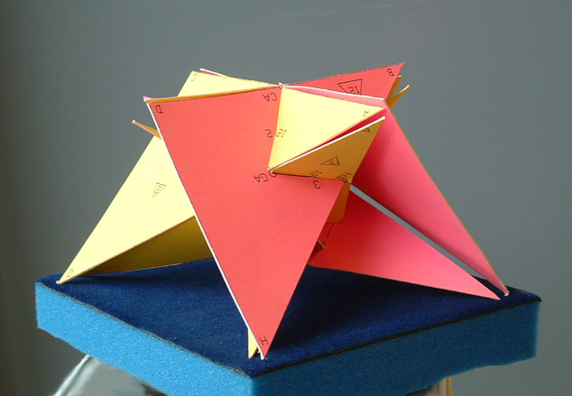
 Simplest
polyhedral Approximation of the Morin Surface by Richard Denner.
Simplest
polyhedral Approximation of the Morin Surface by Richard Denner.
 More images from the Cuboctahedral
Sphere Eversion.
More images from the Cuboctahedral
Sphere Eversion.
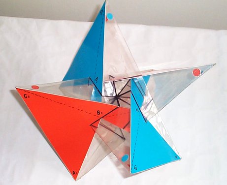
 A
partial cardboard model of the polyhedral Morin Surface by Tien Tan.
A
partial cardboard model of the polyhedral Morin Surface by Tien Tan.
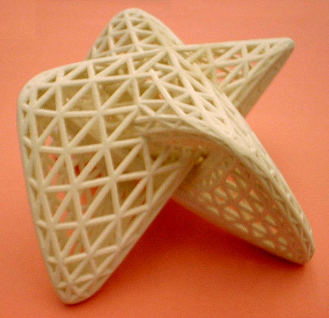 A
3D-print model of the above shape, using a subdivision surface.
A
3D-print model of the above shape, using a subdivision surface.
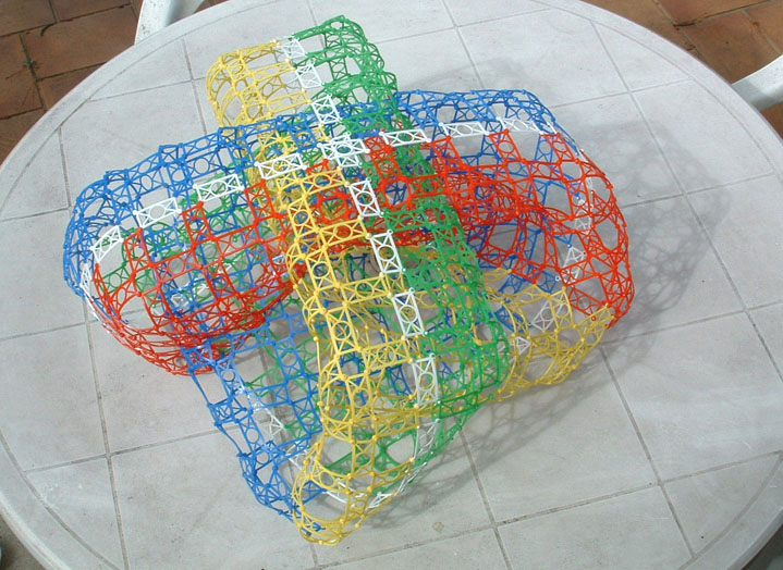 A
first large scale model to study how to approximate the surface with only
a few struts.
A
first large scale model to study how to approximate the surface with only
a few struts.
 Shape
of the surface adjusted to fit the blocks of the snow-sculpting championships.
Shape
of the surface adjusted to fit the blocks of the snow-sculpting championships.
 The
first task in the snow-sculpting competition will be to carve this shape.
The
first task in the snow-sculpting competition will be to carve this shape.
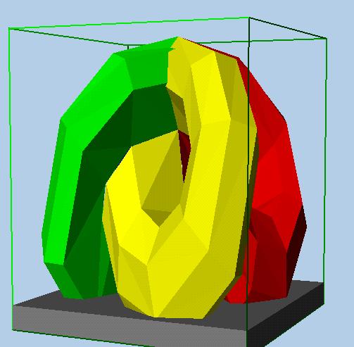
 Low-order
polyhedral approximation of this surface, showing the approximate complexity
that we aim for.
Low-order
polyhedral approximation of this surface, showing the approximate complexity
that we aim for.
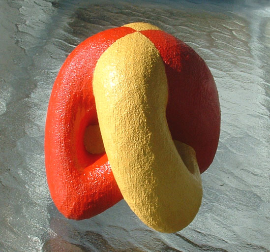
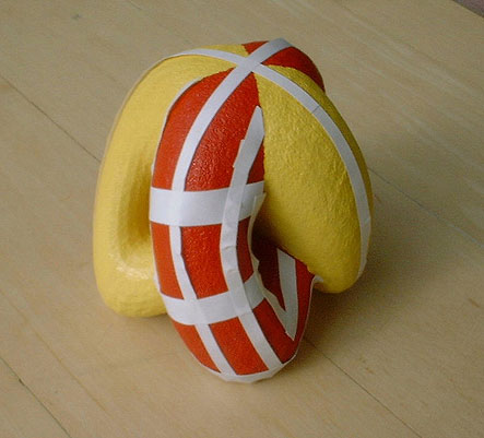 But
we want the various curves to flow smoothly over the original Morin Surface,
as indicated by the tape ...
But
we want the various curves to flow smoothly over the original Morin Surface,
as indicated by the tape ...
 ...
or in this drawing.
...
or in this drawing.
 And
all four lobes should end up in a reasonably large footprint at the base
on top of the pedestal.
And
all four lobes should end up in a reasonably large footprint at the base
on top of the pedestal.
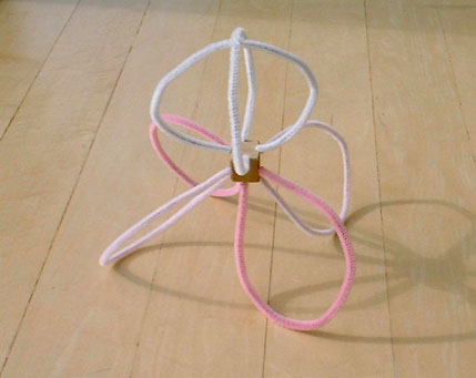
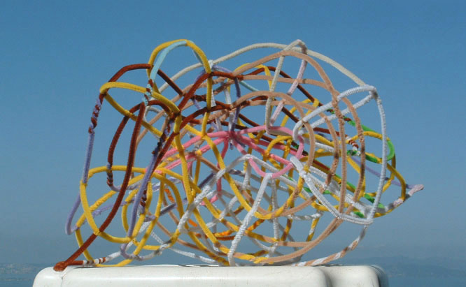 Another
model (made from pipe cleaners) to study the topology and interconnectivity
of the struts.
Another
model (made from pipe cleaners) to study the topology and interconnectivity
of the struts.
One challenge is to model this on a CAD tool, so I can make a maquette.
The few CAD tools I have knowledge of do not have the right primitives.
Alex (my student) and I are currently thinking about modeling each
smooth strut sequence
as a sweep of a trapezoidal cross section along a separate interpolating
spline.
 We
start with a model of all the self-intersection lines in the Morin surface.
We
start with a model of all the self-intersection lines in the Morin surface.
Modeling the basic shape with carefully chosen sweeps along the self-intersection lines
 The
we use a sweep of a cross section, modeled as a Bézier curve, to
create the arms of the Morin surface.
The
we use a sweep of a cross section, modeled as a Bézier curve, to
create the arms of the Morin surface.
This gives more control over the surface shape.
 We
can also readily choose the number of struts and have better control where
they fall.
We
can also readily choose the number of struts and have better control where
they fall.
If only these struts were nicely curved ... !
Also, we need to work on the way that these struts disappear into the
sculpture base.
 -
- -
- Here
is a nice model of the Morin Surface made on the 3D printer, but ...
Here
is a nice model of the Morin Surface made on the 3D printer, but ...
Complexity is still a mayor issue when considering this for a snow sculpture!
Some of the possible variations (simplifications) include: not
opening up all the windows,
perhaps, keeping the surface contiguous and connected through the four
inversion mouths,
and only carving out the windows where the struts start to diverge
dramatically.
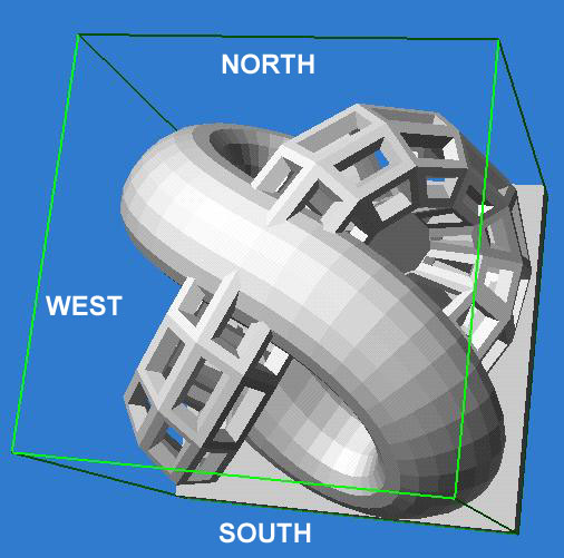
Here is an even more promising option:
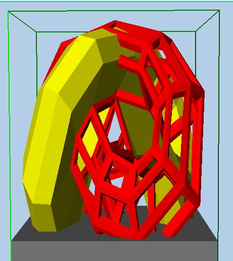 Suppose,
we just carve the struts from two of the lobes, leaving the other two lobes
solid ?
Suppose,
we just carve the struts from two of the lobes, leaving the other two lobes
solid ?
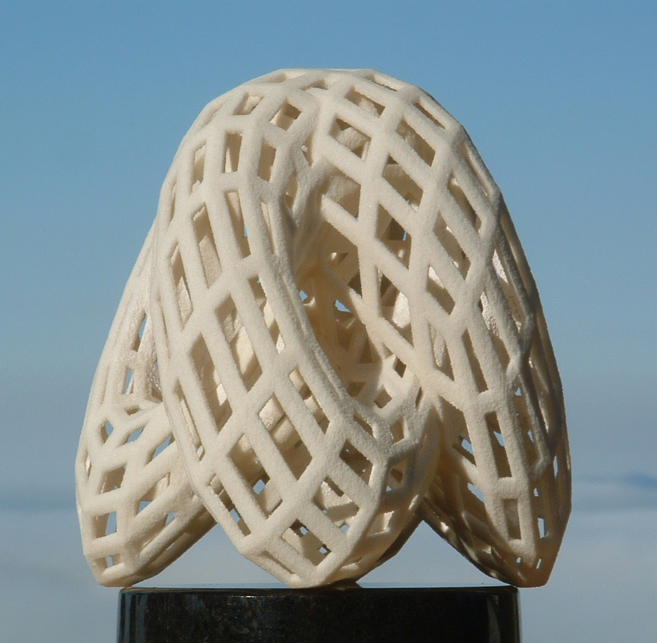
This would also nicely demonstrate that we see two different sides
of this surface.
We can claim that it acts like a "one-way mirror" : from one side it
looks solid, from the other transparent!
This seems quite doable !
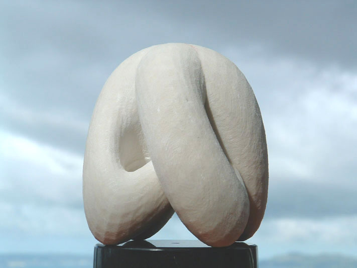
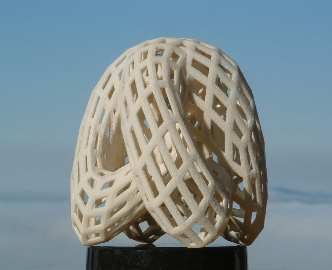
As an intermediate checkpoint, we built a physical model of this
"Half-Morin" surface on the FDM machine.
We can contemplate to stand the surface on its cross junction, so
it opens like a flower in the up-direction.
This upside-down orientation makes this a more "flamboyant" sculpture!
I would not have dared doing this with the full skeleton, but with
the half-skeleton, this should work.
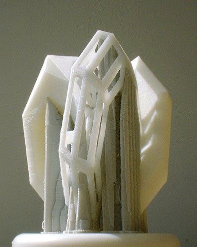 -
- This
is also how the model came out of the machine; all the supports are still
in place.
This
is also how the model came out of the machine; all the supports are still
in place.
 -
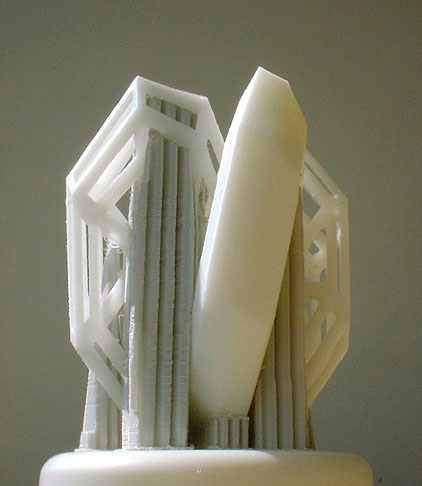
-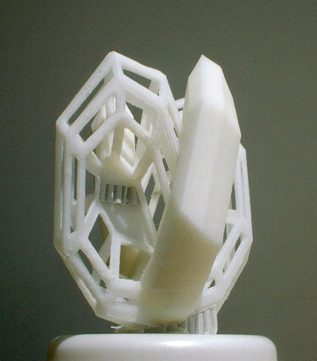 After
partial removal of the supports and some clean-up.
After
partial removal of the supports and some clean-up.
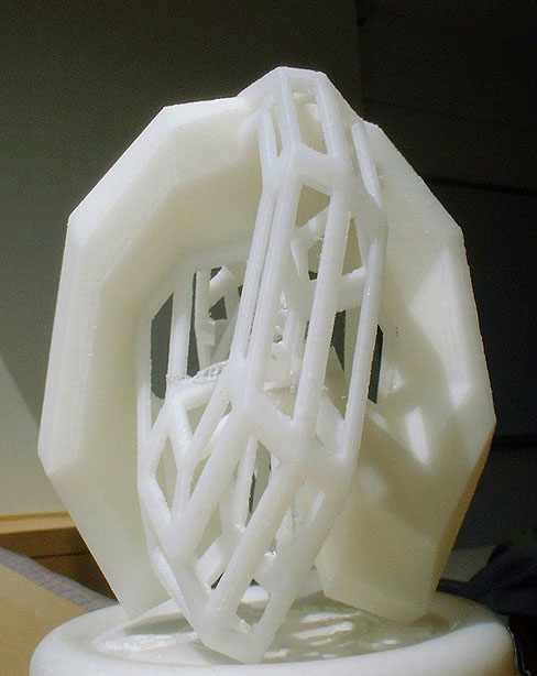 -
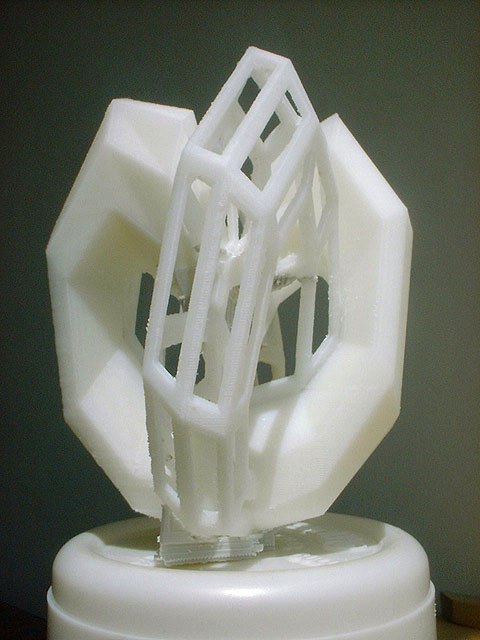
- All
supports removed, and turned upside-down into the original orientation.
All
supports removed, and turned upside-down into the original orientation.
(Note. There was a problem with the fabrication file due to some
unresolved contour intersections.
This accounts for the band of additional gray support material
in the wrong place.)
 -
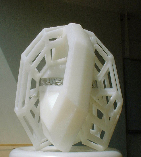
- A
closer look at the intersections between the full and the skeletal branch.
A
closer look at the intersections between the full and the skeletal branch.
I arranged it so that right at that intersection line there is a "rib"
of the skeletal branch; this makes for a nice termination.
Refinement of the strut layout
 -
-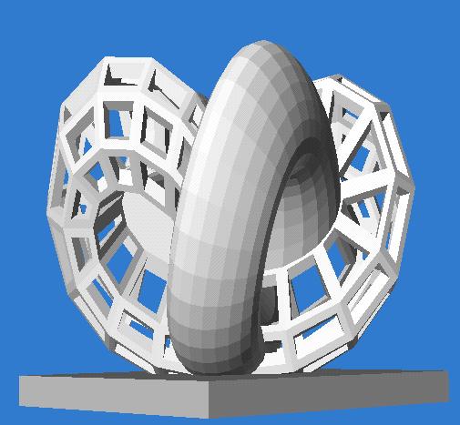 Using
6 longitudinal struts and 9 ribs -- this looks quite elegant !
Using
6 longitudinal struts and 9 ribs -- this looks quite elegant !
 However,
there are some serious structural engineering concerns:
However,
there are some serious structural engineering concerns:
While this shape looks elegant, I now have some doubts whether this
heavy solid "worm" will hold up by itself.
The skeletal branches attached to it will only provide little support
for the "loose" ends of this worm.
If anything, the skeleton would like to have something to lean to and
get some support for itself.
 What
should we do ?
What
should we do ?
Make the struts much thicker ?
or turn the whole thing upside-down again?
In a "bridge" configuration, this crucial worm has a better chance
of holding up.
 -
- -
- Best rendering of current design: two side views and a top view.
 The
latest model under construction in the FDM machine after 2 days.
The
latest model under construction in the FDM machine after 2 days.