Juergen Bokowski also sent me an article "Die Geschichte eines Modells"
in which he describes the difficult path involving the construction of
many temporary models to find a good shape for the surface and pleasing
placement of the vertices and edges, and some
other
publications.
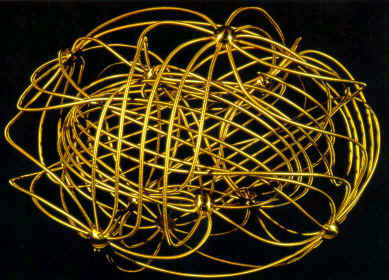
The solution above corresponds to a model with D6 symmetry (one C3
and three C2 axes). It is this topological configuration for which he could
first prove that a corresponding polyhedral object with 12 vertices, 66
straight edges, and 44 plane triangles could not be constructed without
self-intersections. Juergen Bokowski got me involved in this project by
asking me whether I could see a way to make a good computer graphics model
of such a mathematical object which would nicely show the symmetry and
the 44 curved triangular surface patches.
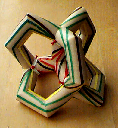
The genus-6 surface can be made of even higher symmetry, i.e. T24, corresponding to the symmetry group of a tetrahedron, and the K-12 graph can be mapped onto it with T12 symmetry, corresponding to an oriented tetrahedron. I was unable to figure out how to place the 66 edges onto such a surface by simply making diagrams or perspective sketches in 2 dimensions; I also needed a physical 3D model to experiment. After contemplating many different materials, I finally used tubular styrofoam pieces, 2 inches in diameter, that are sold by hardware stores as insulating sleeves for warm-water pipes. Twenty-two segments form a 3D graph with five four-fold junction points at the locations of the corners and center of a tetrahedron, and with six handles corresponding to its edges. At a diameter of 14 inches, the model was easy to handle, yet open enough so that I could comfortably access all points on its surface.
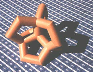
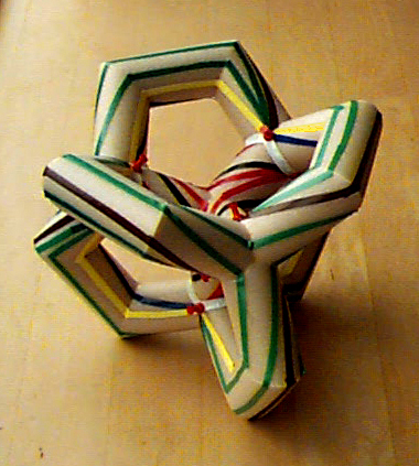
First I contemplated using marker pens or wires to show the placement of the edges, but I then used thin strips of colored adhesive tape. On the styrofoam surface, they can be applied and removed easily, and their bright colors make it easy to track edges that wind around one of the tubular segments. Randomly placing 12 vertices and then trying to connect them could end up to be a very tedious task. Judicious use of symmetry not only makes this task much easier, but it also leads to a more pleasing and easier to understand model. The 12 vertices could either be placed as 6 pairs in a C2-symmetric configuration around the centers of the 6 handles, or they could be placed in a C3-symmetric manner around each of the 4 arms of the central tetrahedral junction. I chose to place them at the 12 monkey saddle points where two handle surfaces meet with one arm from the central junction:
This gives the most room around each vertex to place the eleven emerging
edges.
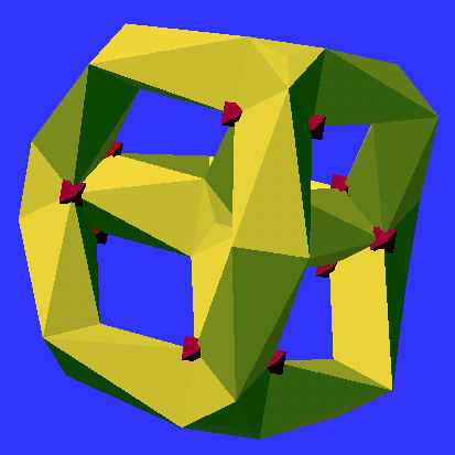
Further contemplation of the symmetry of this object made it clear that each of the eight C3-axis points on the surface had to correspond to the center of three-fold symmetrical triangular face -- possibly drawn out into an extended and warped "starfish" shape. Moreover, three different types of C2-symmertical edges had to run through each of the 18 surface points where the three C3 axis penetrated. While this placed many constraints on the edges, it still took me three tries to find a scheme that would properly connect every vertex with evey other one, and then two more refinements to make the edges look as simple and pleasing as possible. The key degree of freedom here is the amount of twist that one assigns to the edges on the four branches of the central tetrahedral junction. First I started here with the simplest possible pattern, which then forced more twist onto the already rather long edges spiralling along the outer six handles. I then realized, that the trick is to make the outer four C3-triangles (outlined by the green edges) as simple as possible, and then pick up whatever twist is necessary on the inner four branches. The most twisted inner edges (shown in black), then each make two 180-degree turns around their respective branches. All but one set of 12 triangles, can now be traced rather effortlessly by visual inspection from a static viewpoint.
Now the challenge is how to convert this into beautiful computer graphics model ...
CHS 7/14/99